RGB Scooter
RGB Scooter
I don't need to explain why I did this, do I? Putting lots of WS2812 RGB LEDs on everything is a common thing to do, and this of course applies to scooters. However, I was not fully satisfied with the existing projects, since most of them were just boringly shining in all colors.
Features
This scooter is different! It can not only light your way in the dark, but it can do so synchronized to your driving speed! Yes, it has a tacho and allows for LED effects that "are locked on the ground", with the scooter hovering above them.
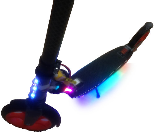

Here is the full feature list:
- Hall-sensor based speed measurement on the rear wheel.
- Software compensation for inaccurately placed magnets.
- 8 different bottom light effects and two front/side lighting programs.
- Multi-function user button to switch between effects and to adjust the brightness.
- LiPo battery monitoring with cell autodetection: The front lights display the number of cells, the side rainbow lights display the battery level
- Battery protection: When the battery is empty, the lights are shut off almost completely, only flashing for your attention sometimes. This reduces the current drain to about 50mA.
Bill of materials
Most components are easily available at your favourite chinese marketplace:

(20-30 EUR)
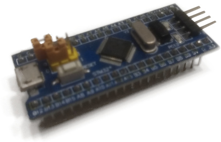
(2 EUR)
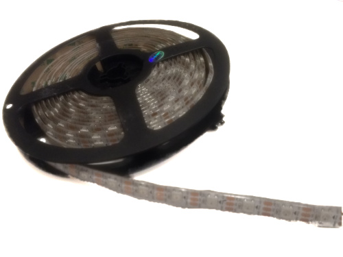
(ca. 20 EUR for 4 meters)
(10ct)
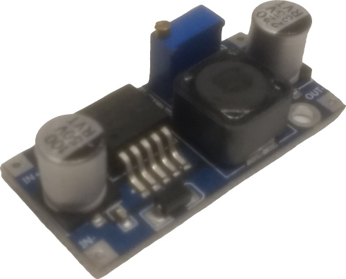
(1 EUR)
(1 EUR)
(3 EUR)
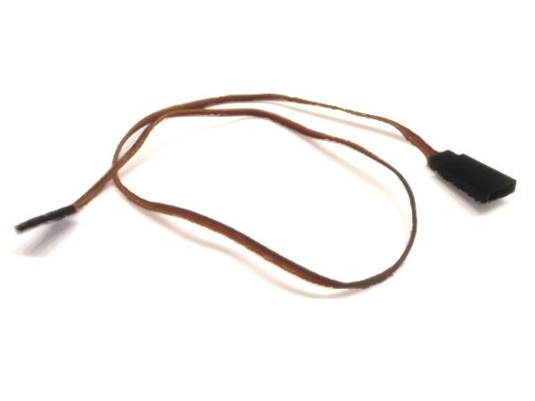
(3 EUR)

(10 EUR)
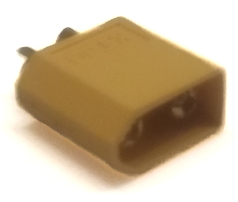
(1 EUR)

(2 EUR)
(?? ct)
Building instructions
LED strips
Glue them wherever you want and daisy-chain them as follows: side1, front, side2, bottom1, bottom2. Note that bottom1 goes to the rear, while bottom2 goes back to the front. Similar for the side lights. You can use loads of hot glue to fixate the wiring.
Blue pill board
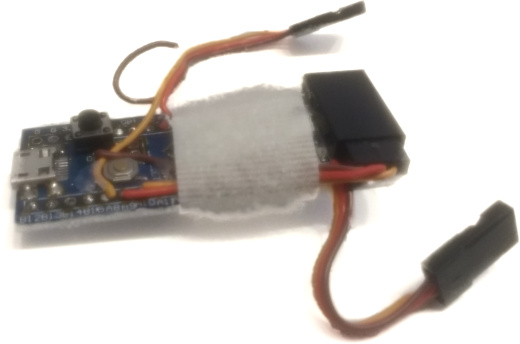
Remove all pins (including the BOOT0/1 pin header). Solder BOOT0 and PA10 together, and glue a push-button onto the board that shorts these two pins with 3.3V. For convenience, you might want to solder two male 3-pin servo cables to PA7 and PA8 (tacho and led data) and to +5V, GND and PA0 (DC/DC-regulator connection and battery measurement). Also add a female socket for the UART to PA9,PA10,GND and glue it to the board.
Tacho
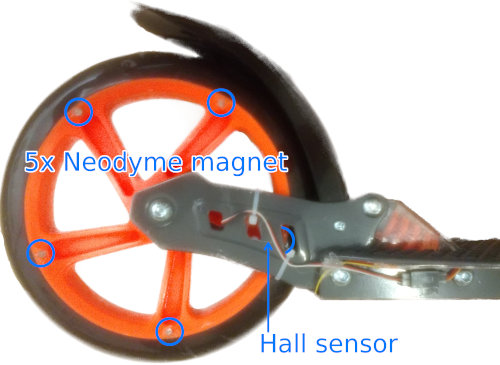
Glue an arbitrary number of neodymium magnets (I used 4x4x1mm) to the rear wheel and place the hall sensor such that it can detect the magnets. You don't need to be too precise, any jitter of the magnets can be corrected in software.
DC/DC-converter and battery measurement
Solder a XT60 connector (or your favorite battery connector) to the input terminals of the LM2596 board. Also solder two resistors to the input terminals like below and connect (*) with the battery measurement pin(PA0).
(+)---[100kOhm]---(*)---[10kOhm]---(-)
Other stuff
Hot glue, velcro tape and zip ties are your best friend.
Schematics
Learning the magnet distance
It is difficult to glue the magnets perfectly equally spaced and failure to do so results in a noisy speed estimate. This problem is illustrated in the graphics below, which show a continuously spinning wheel which is slowly decelerating due to friction. The colored dots signify which magnet caused the current reading.
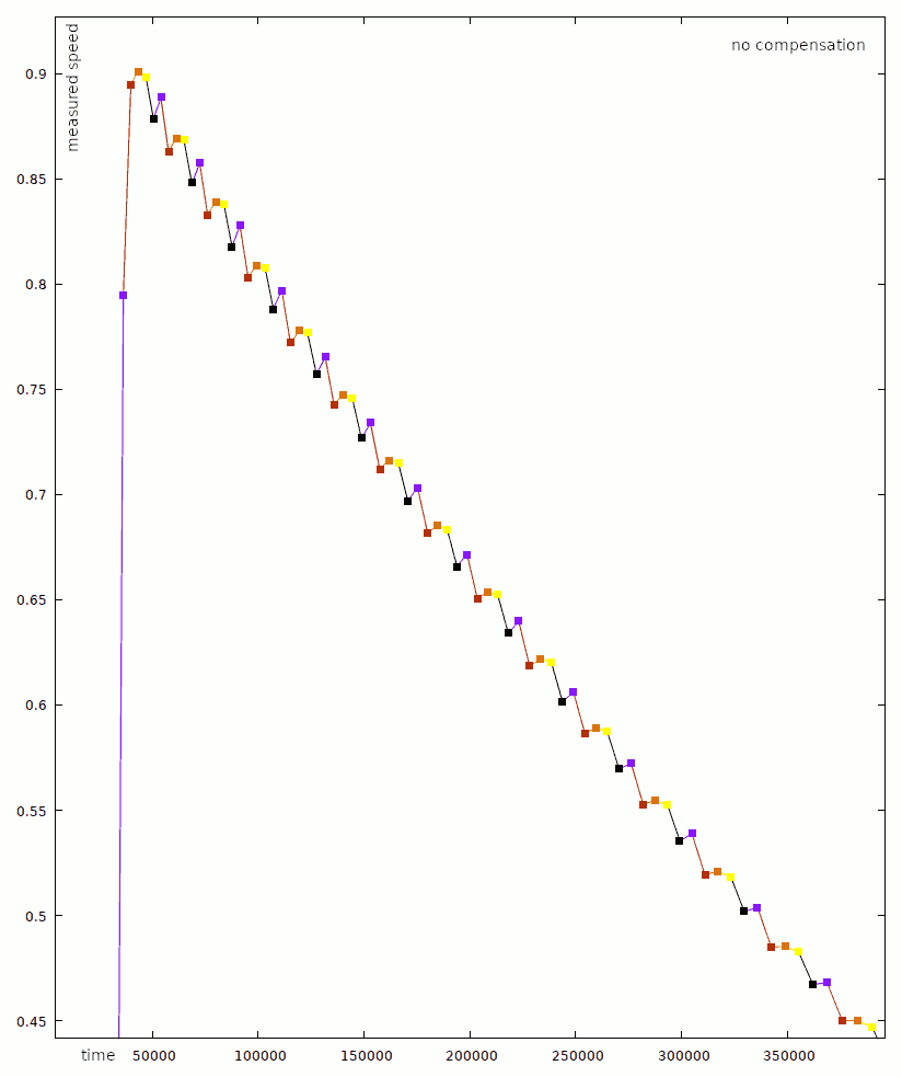
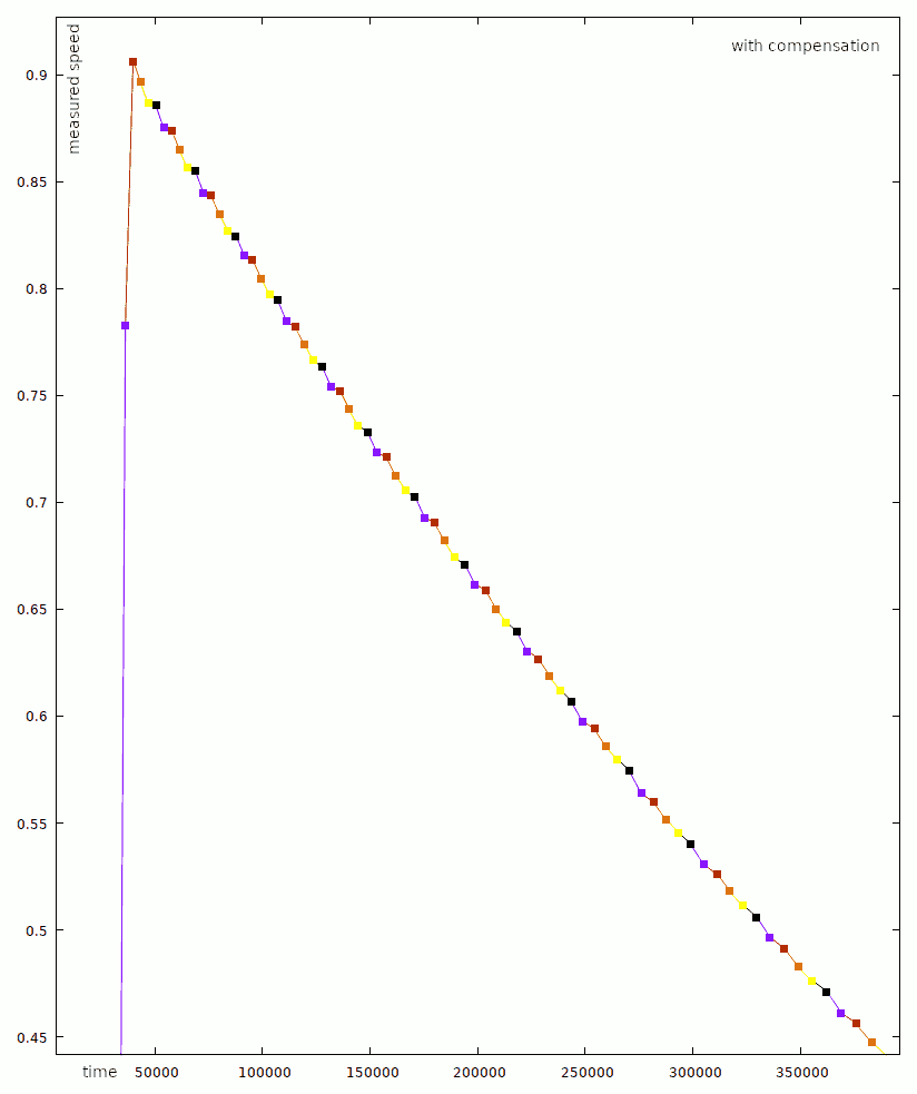 Easily, one can recognize a repeating jumpy pattern in the left, uncompensated graph, while the compensation produces a quite smooth graph on the right.
A small python tool (learn.py) reads the raw timing data recorded from the scooter while the wheel is spinning. It takes the wheel's deceleration due to friction into account and outputs the required calibration
data for the firmware.
Source code
The source code and building instructions are freely available on GitHub.


