
AVR Tetris for the oscilloscope
AVR Tetris for the oscilloscope
Introduction
What's this?
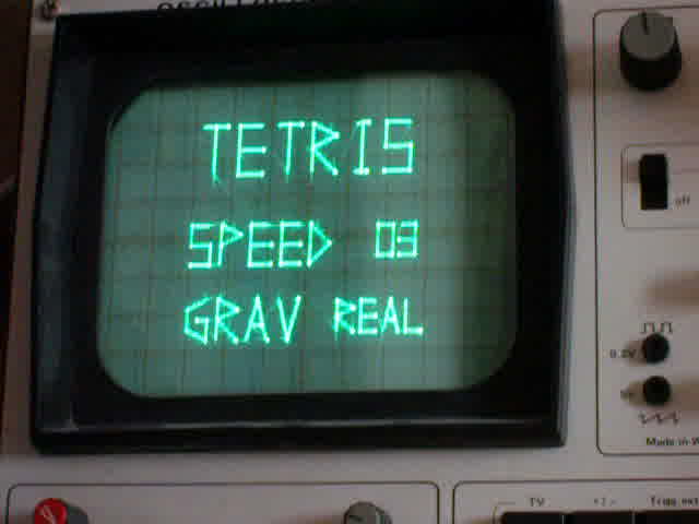
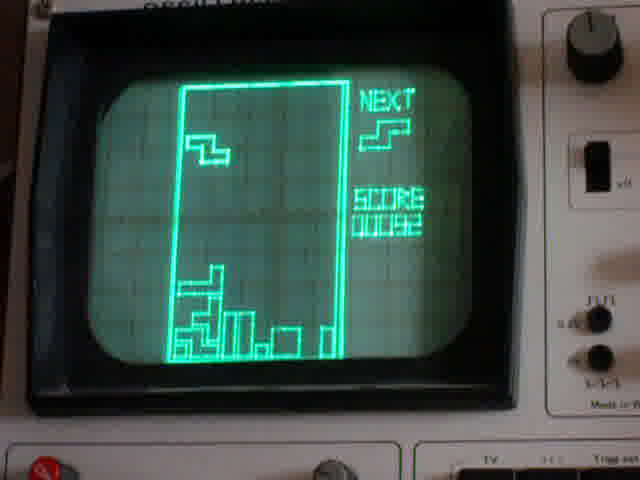
This is a project allowing you to play tetris on an oscilloscope!
How does it work?
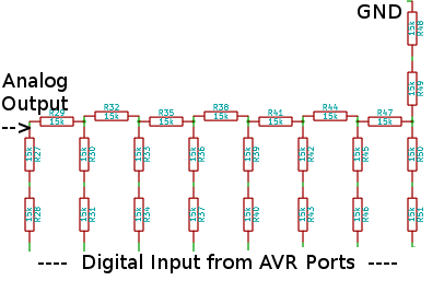
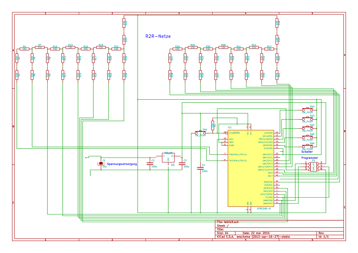
The game logic is driven by an Atmel Atmega8 AVR microcontroller, which has access to five push-buttons to control the game. For displaying, two 8-bit output ports of the AVR are wired to two digital-analog-converters (DACs), which then are connected with the X- and Y-input of an oscilloscope. This way, the light beam can be moved freely, and can be used for painting the playing field.
The DACs are implemented as simple R2R-nets or resistor ladders, consisting only of resistors of a size X kOhm and 2XkOhm; in practice, I am only using one kind of resistors, the 2XkOhms are realized by putting two resistors in series.
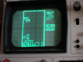
See it in action
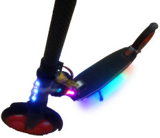
In this and this YouTube-Videos you can see the Tetris in action, running on my beloved Hameg HM 312 Scope.
Features
- Main menu with adjustable speed and gravity type
- Fancy graphics with some effects
- Scorekeeping and score display using a vector font
- Two types of gravity: The original "naive" tetris gravity, where bricks can be floating in the air, and a "real" gravity type, where deletion of a line might lead to more brick parts falling down, possibly filling and deleting even more lines.
- Oscilloscope vector graphics :), as shown below:
The software
The whole software is written in C, without the use of inline-assembly.
Drawing lines
Lines are drawn by (more or less) slowly moving the light beam. The Bresenham line drawing algorithm is used for this.
While one could have used simpler loops for horizontal and vertical lines, this is a bad idea because, since they will run faster, the lines will be darker on the scope's screen.
Setting the beam to a certain location is as easy as PORTB = x; PORTD = y;, since the DACs occupy a complete port each.
Font
The on-screen-display font for the scores and the menu were created with a rather obscure tool I've written for this purpose. Each character is stored as a series of bytes, each byte is encoding one point in a 8x16-raster. The highest bit encodes whether to move the beam visibly ("slow") or invisibly ("fast"), the next three bits encode the x-position, and the lower four bits store the y-position.
Storing bricks
Bricks store their x- and y-location in two bytes, and their blocks are stored as bit-map in four bytes (one per line; a brick can occupy at most four lines). For example, the T-shaped block is 0x00,0x00,0x07,0x02.
Several brick management functions make the use of this data structure, rotating, and checking for collision with the playfield's bitmap easy.
Drawing the bricks
For each brick separately, its outline is drawn; this works by following the "edges" of the brick, and drawing them with a certain margin
Buttons
The buttons are wired to PORTC (which does not offer the full 8 pins, therefore being unusable for driving the beam coordinate). The input function debounces the buttons by waiting for the button state to be steady for at least 3 cycles.
The hardware
Disclaimer
Warning:I wrote this page four years after having finished this project! While I try to get everything here right, do not follow the instructions, schematics, etc blindly, but double-check everything against the appropriate datasheets. Any damage which might occur to any hardware or anything else is solely in your responsibility. By using any information on this page, you agree to this. You have been warned!
Engine
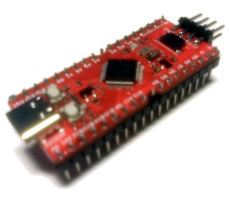
The engine of the whole project is the Atmega8 microcontroller, which offers 8kiB of flash memory as well as 1024 bytes of RAM. Also does it offer 23 input/output pins, which are almost completely occupied by the two 8-bit DACs and the 5 buttons.
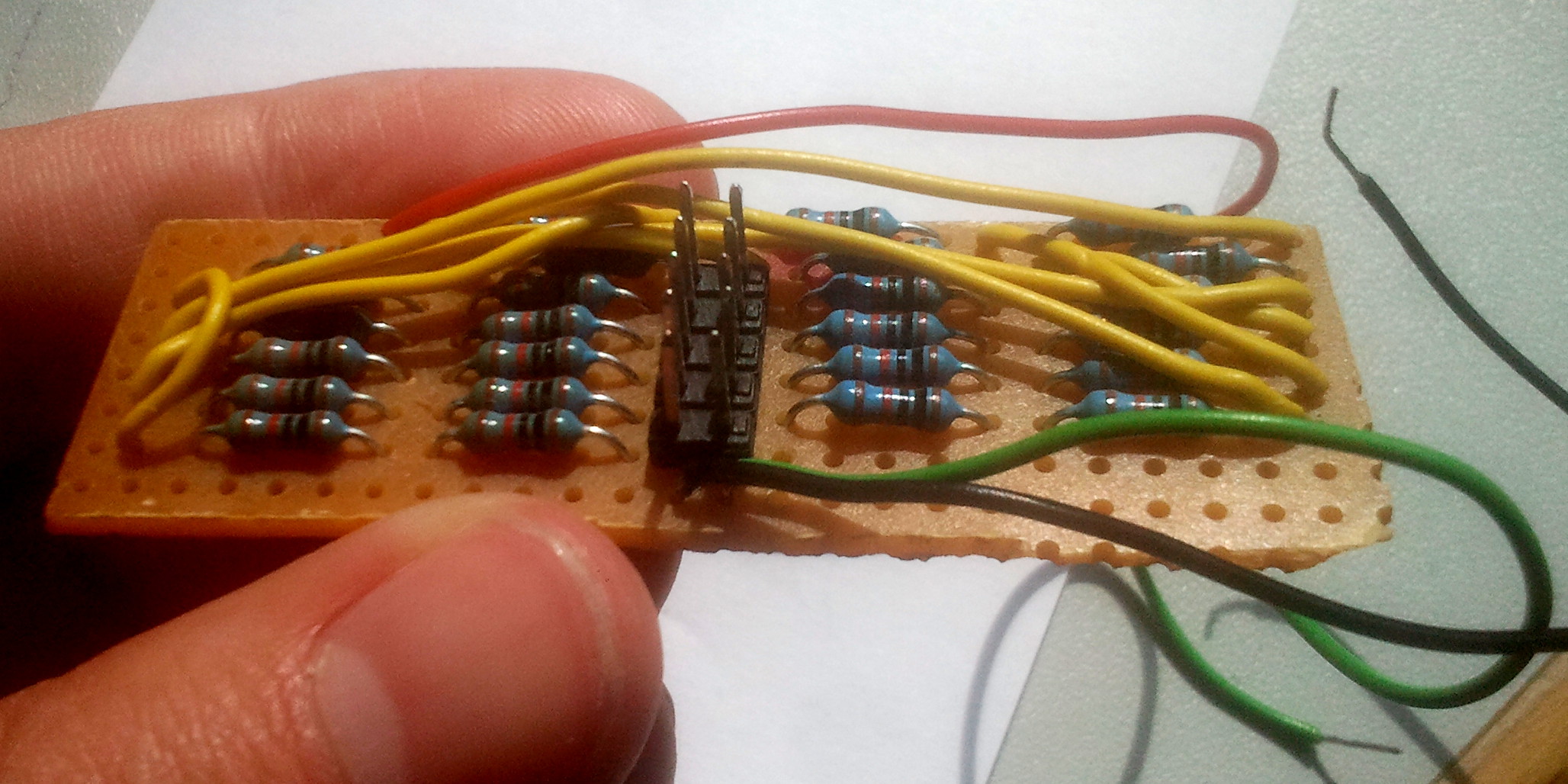
The DACs
As stated above, two 8-bit R2R-nets are used as DACs; they're wired to PORTB and PORTD. Below is the schematic of one DAC:
Version 1 on the STK500
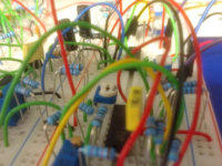
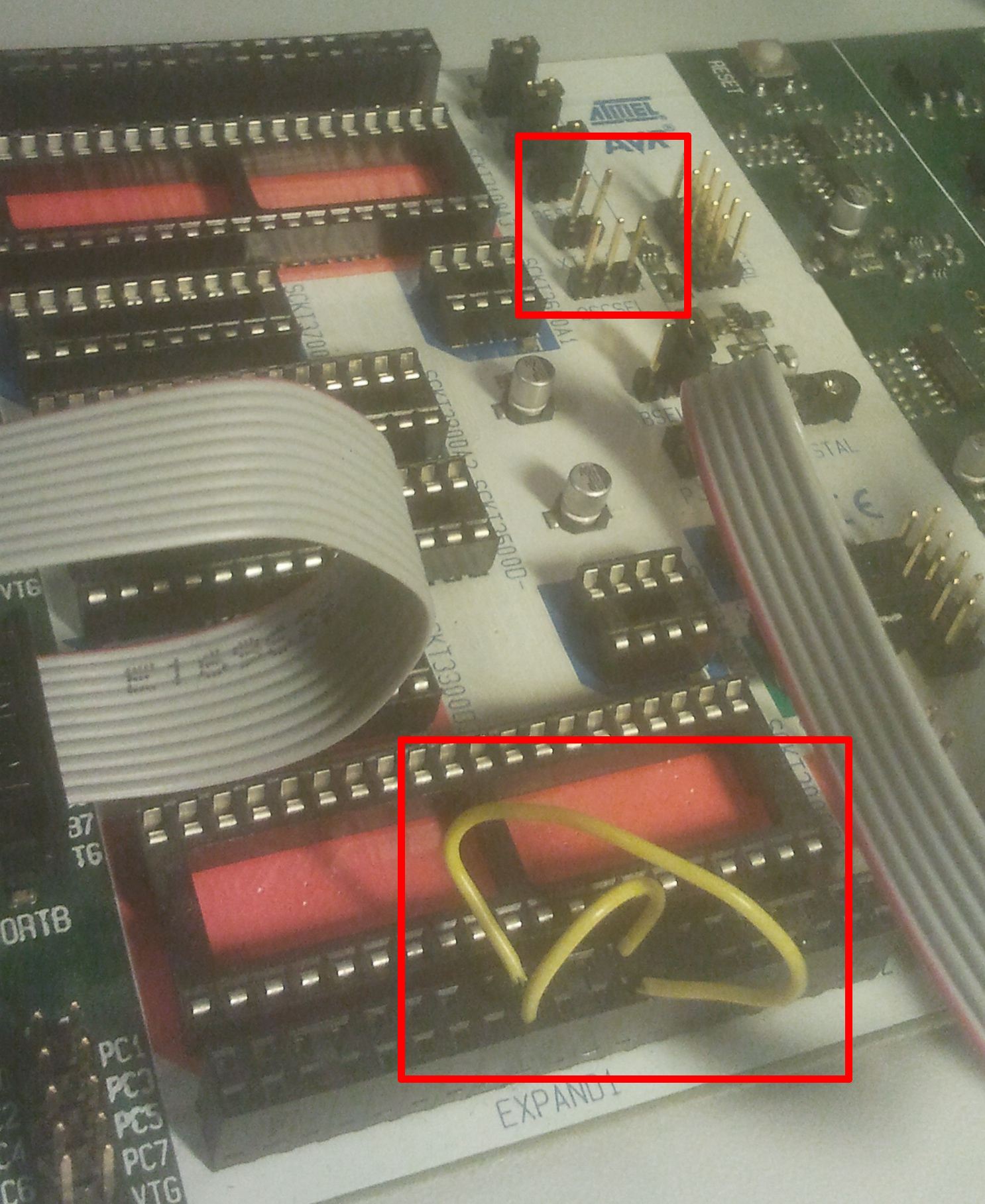
The first and development version of the project was built on the STK500 evaluation board. Using the 2x5pin port connector cables, the AVR's ports could be connected with the DACs which were build on 0.1 inch hole matrix boards with the resistors soldered:
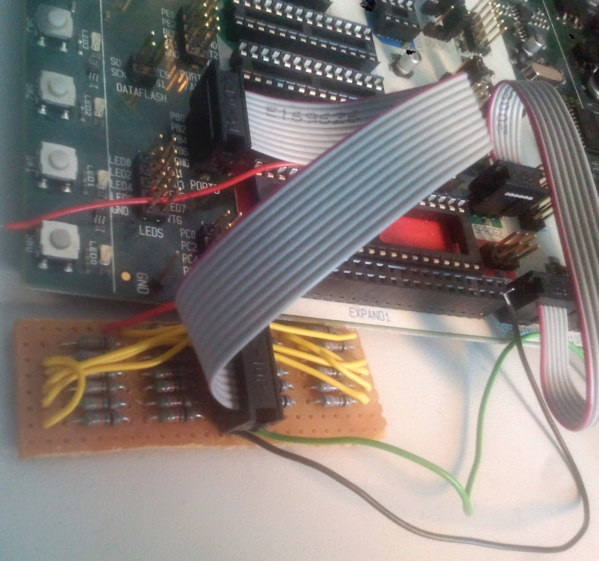
In order to make everything work, however, some setup is necessary: Remove the XTAL jumper of the STK500 to disconnect the board's clock net from the AVR; the Atmega8 must be driven from its internal oscillator. Then, one has to make two connections on the Expansion Connector 1 header: (XT1 (17) -> PB6 (24)) and (XT2 (18) -> PB7 (23)). (Warning: Making the wrong connections could lead to permanent damage on your STK500, your microcontroller or other hardware! I might have gotten the connections wrong, so double- check them against the STK500 handbook prior to testing them out. You have been warned!)
Version 2: Printed PCB
I also designed a PCB (my first PCB, btw :)), using SMD components. I must admit that I have still not soldered it together, but some day, I probably will.
You download the schematics and the PCB layout in the Downloads section
Downloads
This software is released under the GPLv3 or any later version. See the zipfile for further details.
Software
Better get the complete package. There is also a .hex-file for the ATmega8, and the C source alone available.
Schematics
I've created them in KiCAD. There is the tetris-schematic.sch source file, as well as a SVG plot and a PNG file.
PCB Layout
Also created with KiCAD. tetris-pcb.brd source file and a mirrored postscript export.
